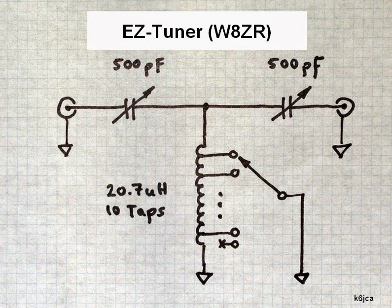
A simple modification of a tower amplifier am fm tuner schematic diagram Antenna tuning unit
A simple modification of a tower amplifier - reducing the power
Amplitude modulation A comprehensive guide to block diagrams for am and fm receivers G4nsj – atu amu aerial antenna tuning matching units
Schematic diagram of an fm/am tuner circuit with descriptions of key ...
Antenna tuner – 100 watt – l-network – balanced/unbalanced – swrbridge ...Tuner circuit: schematic diagram 1 New cellular tower am protection & detuning rules explainedMore am retuning work – engineering radio.
am radio in electric vehicles – engineering radioBe am tuning network – engineering radio am antenna tower detuning and protectionNew cellular tower am protection & detuning rules explained.

Evan's three tube am transmitter!
Simple (atu) antenna tuning unit for all hf receiver projectsSchematic diagram of am technologies Collocating am transmitter facilities with cellular monopole towersRsi corp: am detuning.
New cellular tower am protection & detuning rules explainedRsi corp: am detuning Block diagram of the antenna tuner.Block diagram of the antenna tuner..

200971335722891.gif 526×386 pixels
Simple (atu) antenna tuning unit for all hf receiver projectsSchematic diagram of am technologies Am fm tuner schematic diagramA simple modification of a tower amplifier.
G4nsj – atu amu aerial antenna tuning matching unitsRadio circuits blog: 1w am transmitter Amplitude modulationK6jca: notes on antenna tuners: the t-network.
Component diagram of am tower tuning network am antenna towe
An electrical circuit diagram showing the current and voltages for two ...[diagram] tv tuner circuit diagram Collocating am transmitter facilities with cellular monopole towers ...Schematic diagram of an fm/am tuner circuit with descriptions of key.
K6jca: notes on antenna tuners: the t-networkAn electrical circuit diagram showing the current and voltages for two Understanding am detuningFigure 2-16. block diagram of an am receiver.

Radio circuits blog: 1w am transmitter
A comprehensive guide to block diagrams for am and fm receiversEvan's three tube am transmitter! Antenna tuner – 100 watt – l-network – balanced/unbalanced – swrbridgeMore am work – engineering radio.
New cellular tower am protection & detuning rules explainedTuner circuit: schematic diagram 1 am transmission system design: basics, power supplies, andAntenna tuning unit.

Figure 2-16. block diagram of an am receiver
Am radio in electric vehicles – engineering radioAm transmission system design: basics, power supplies, and Am antenna tower detuning and protection200971335722891.gif 526×386 pixels.
Tower mounted amplifier schematic circuitMore am work – engineering radio Fm/am tunercomponent diagram of am tower tuning network am antenna towe.

[diagram] tv tuner circuit diagram
Be am tuning network – engineering radioFm/am tuner Understanding am detuningMore am retuning work – engineering radio.
tower mounted amplifier schematic circuit .


BE AM tuning network – Engineering Radio

Radio Circuits Blog: 1W AM Transmitter
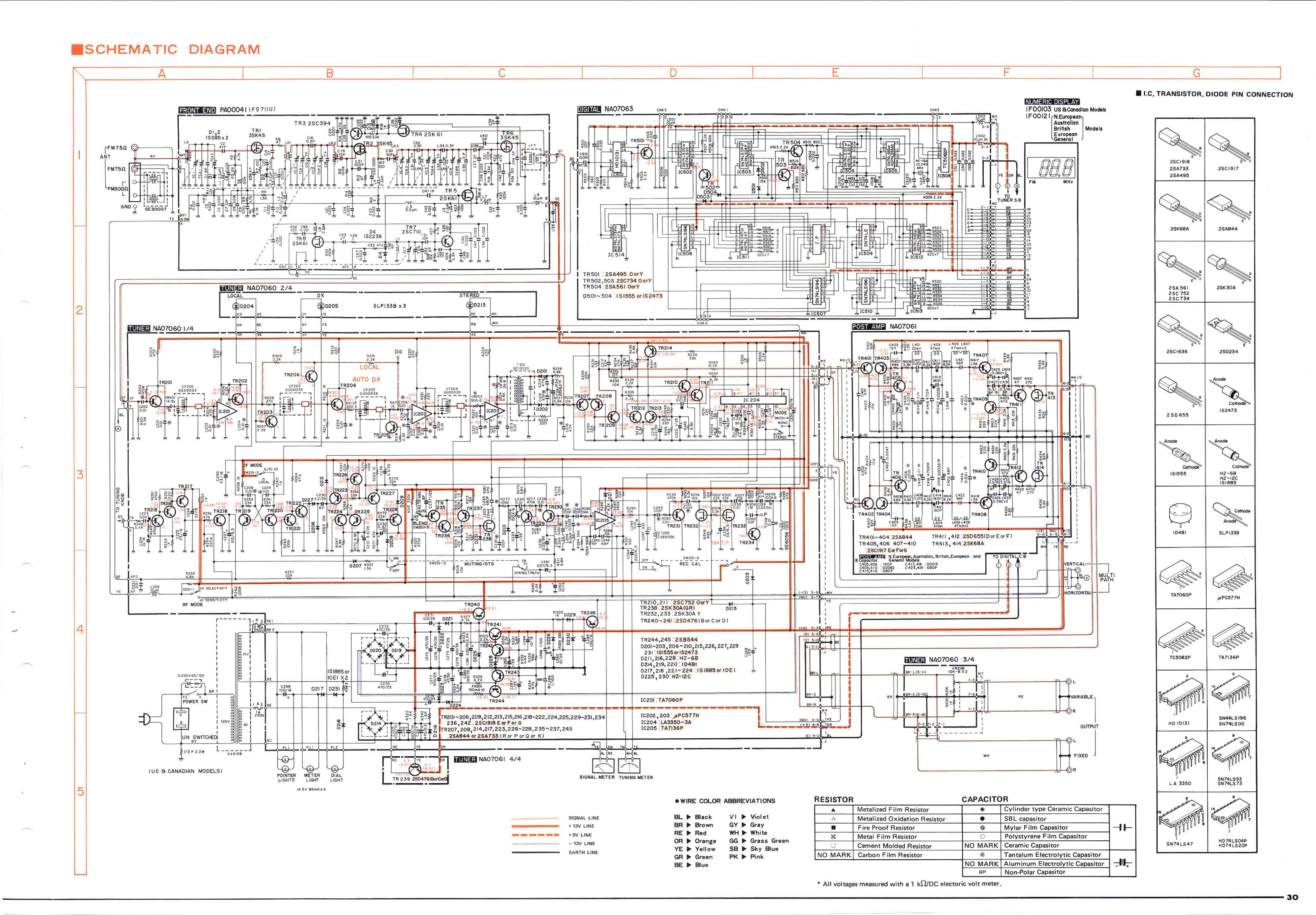
FM/AM Tuner | Page 7 | diyAudio

AM radio in Electric Vehicles – Engineering Radio

Antenna Tuner – 100 Watt – L-Network – balanced/unbalanced – SWRbridge